Reverse engineering the CAN bus on my 2009 Suzuki Swift Sport

As long as I can remember, I’ve always had a passionate interest in two things: computers, and cars.

It might come as a surprise then, that I have never fully, until now, explored how modern vehicle CAN bus systems work. I decided I would reverse engineer the CAN network between my cars control modules, I could then use what I have learned to write an application that injects new commands into the network that the car believes is coming from another control module.

I started by buying myself a CAN adapter that was compatible with Linux. canable.io was my choice, I bought a cheap clone, as the hardware is open-source. It is compatible with the python-can library, and the can-utils set of packages within Linux, so it was perfect for my needs. As it happens, I already have a Raspberry Pi 5 with HDMI wired into my Pioneer head unit, so I will use this as the basis to run the code for the project, don’t ask…

I now needed to do some research into how to connect to my cars specific CAN bus. I determined via this forum post and this website, that I could access the CAN bus on OBD pins 6 and 14, for CAN HIGH and CAN LOW, at a data rate of 500kbps.

I connected the canable to my Pi and ran the below command, this listens on the network via the can0 interface:

sudo cansniffer can0

Success! The Canable was listening on the network, and I could now see packets flowing through the network. (I have blurred the majority of the above image as it is quite possible that it contains my VIN number in hex format)

It’s important to note that on a CAN network, each message has an ID that tells other modules what the message is for, followed by bits of information that can be anything such as an unlock command, steering wheel position, speed, throttle position, engine temperature. The list goes on…

It turns out that my Suzuki is actually pretty basic by modern standards, and I believe most buttons within the car, (I.e window switches, headlights etc), are all controlled directly via the physical switch and a relay which opens the circuit. The body control module does seem to report on the network, and I was able to make the gauge cluster believe the lights are on by replaying that constant “lights on” packet, however when I stepped outside the car they were still off, the switch has to be in the physical on position for the lights to switch on. I would love to explore a modern BMW or VW in the future, however my simple and older Japanese cars do not have the same amount of computerization!

Finding CAN ID’s and messages is simply a case of running CAN sniffer, and opening doors, pressing buttons etc, and seeing what data changes. I found the below ID’s and data for my Suzuki, I would imagine this applies to most Suzukis built 2000-2015.

3D8#000500 - All Doors lock - Send once to toggle dome light (for some reason??)
3D8#000100 - All Doors unlock
3D8#000200 - Driver door unlock

3D8#000501 - Door Lock with single hazards
3D8#000202 - Door unlock with double hazards
3D8#000020 - Start door buzzer
3D8#000000 - Stop door buzzer

3D8#000001 - 3D8#000002 repeatedly = flash hazards

Fairly certain that ID 3D8 is the Body Control Module mounted under the dashboard.

For our ultimate goal of writing a demo application that is able to inject commands into the network, I would use python, with the Flask library, to create a webapp with buttons that would run commands. The canable adapter also has a python library with documentation.

The code I wrote is as follows:

from flask import Flask
from flask import request, render_template
import requests
import can

interface = "socketcan"
channel = "can0"

# Comment out below if using socketCAN
bus = can.Bus(channel=channel, interface=interface)

# Uncomment below if using slcan interface
#bus = can.interface.Bus(bustype="slcan", channel="/dev/ttyACM0", bitrate=500000)

app = Flask(__name__)

@app.route("/", methods=["GET", "POST"])
def index():
    if request.method == "POST":
        if request.form.get("unlockDriverDoor") == "Unlock Driver Door":
            print("[!] Unlocking Doors") 
            requests.post("<NTFY URL HERE>",data="🔓 ZC31S Doors Unlocked".encode(encoding='utf-8'))
            msg = can.Message(arbitration_id=0x3D8, data=[0, 2, 2], is_extended_id=False)
            try:
                bus.send(msg)
                print("[*] Driver Unlock Command Sent")
            except can.CanError:
                print("[*] Message Error")
            
        elif request.form.get("unlockDoors") == "Unlock Doors":
            print("[!] Unlocking Doors")
            requests.post("<NTFY URL HERE>",data="🔓 ZC31S Doors Unlocked".encode(encoding='utf-8'))
            msg = can.Message(arbitration_id=0x3D8, data=[0, 1, 2], is_extended_id=False)
            try:
                bus.send(msg)
                print("[*] Unlock Command Sent")
            except can.CanError:
                print("[*] Message Error")
 
        elif request.form.get("lockDoors") == "Lock Doors":
            print("[!] Locking Doors")
            requests.post("<NTFY URL HERE>",data="🔐 ZC31S Doors Locked".encode(encoding='utf-8'))
            msg = can.Message(arbitration_id=0x3D8, data=[0, 5, 1], is_extended_id=False)
            try:

                print("[*] Unlock Command Sent")
            except can.CanError:
                print("[*] Message Error")

        elif request.form.get("hazardFlashers") == "Hazard Flashers":
            print("[*] Activating Hazard Lights")
            requests.post("<NTFY URL HERE>",data="⚠ ZC31S Hazard Lights Toggled".encode(encoding='utf-8'))
            msg = can.Message(arbitration_id=0x3D8, data=[0, 0, 2], is_extended_id=False)

        else:
            pass
    return render_template("index.html")

This enabled me to control the locks and flash the hazard lights remotely from a mobile device on the same network. I recorded a demo here where I unlock the drivers door using the webapp running locally on the Pi:
Mikrotik eBGP lab

I am always trying to familiarize myself with different technologies, vendors, protocols, tools and techniques. This is why today I will be exploring BGP, specifically eBGP.

BGP or Border Gateway Protocol is what the internet relies on. Your ISP uses BGP to peer with other ISPs and services (for example Google). BGP dynamically advertises routes to other routers.

This post isn’t intend to be a tutorial and I’m assuming you have basic BGP knowledge, this is just to demonstrate a basic Mikrotik setup.

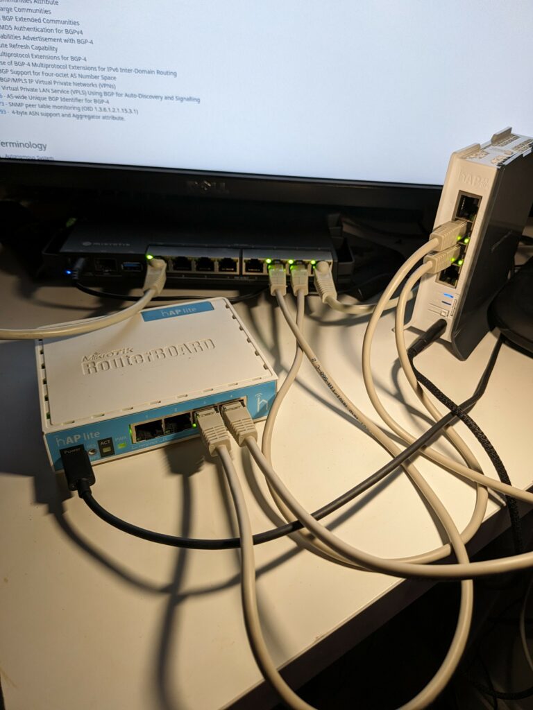
I used 3 routers, a hAP lite, a hAP AX lite LTE6, and an RB5009.

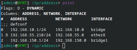
I started by assigning each routers respective ports an IP link between each router, for example 192.168.150.1 for ether7 on port 7 of the RB5009, 192.168.150.2 on port 2 of the hAP AX, and 192.168.151.1 on port 3 of the hAP AX and 192.168.151.2 on port 4 of the hAP lite etc etc.

Then we can start creating our BGP connections. My ASN numbers will be as follows:

AS65000 – RB5009

AS65001 – hAP AX lite

AS65002 – hAP lite

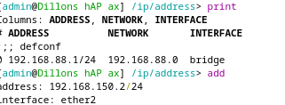
We can add this, and the respective link addresses for each router respectively in the Mikrotik webfig interface:

We repeat this for all 3 routers in the respective web interfaces.

Now, we need to advertise some routes to the other routers, since the RB5009 is also connected to my home LAN, I will use it to demonstrate.

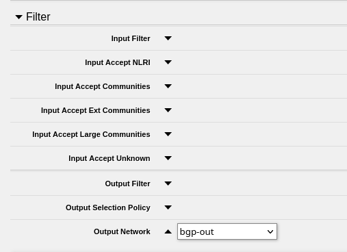
Open the BGP page and open the “Filter” section, then we create a new Output Network, this can be called what you like. Mine will be called “bgp-out”.

We then go into the IP -> Firewall -> Address Lists tab and click “Add New”. Then set the address range you would like to advertise to other routers, and set the list to the “bgp-out” network that we created:

I setup 2 networks, 192.168.55.0/24, which is my home LAN accessible on port 8 of the RB5009, and 192.168.10.0/24 which is the RB5009’s own LAN:

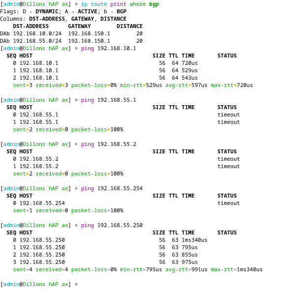
We can now test our setup by connecting to the other routers and checking those networks are reachable:

Success! We can now ping my LAN subnet and the RB5009’s subnet even when connecting through the hAPs! The routes are being advertised.

Experimenting with Intune

In this post I will be learning about Intune deployment. I have pre-deployed a fresh Windows 11 test device onto my Hybrid Active Directory domain (Azure AD is synced with On-Prem Domain Controller), in this post I will do a basic intune setup, and then enroll the device into intune, and apply a basic policy.

(Old) Thinkpad T420 test machine

This guide assumes you have the following:

  1. A Hybrid Azure AD domain
  2. Office 365/Azure AD accounts with the relevant Office licenses (I am using a Enterprise Mobility + Security E5 trial license).
  3. A Windows 11 device joined to your domain and logged into a domain account linked with the license mentioned above.

1. Install Company Portal and enroll the device

To install company portal, you must login to Microsoft Business Store in a browser, search for “Company Portal” and install it onto your device as shown below

Company Portal on Business Store

When company portal has installed, open the start menu, open Company Portal, sign in, and enroll your device onto intune as shown:

Company Portal after enrollment

The device is now successfully connected to Intune. You can automate this process through Active Directory, however, since I am using a trial license for learning, I do not want to enroll all of my domains computers into Intune, so I did the above manual process.

2. Check out the endpoint manager

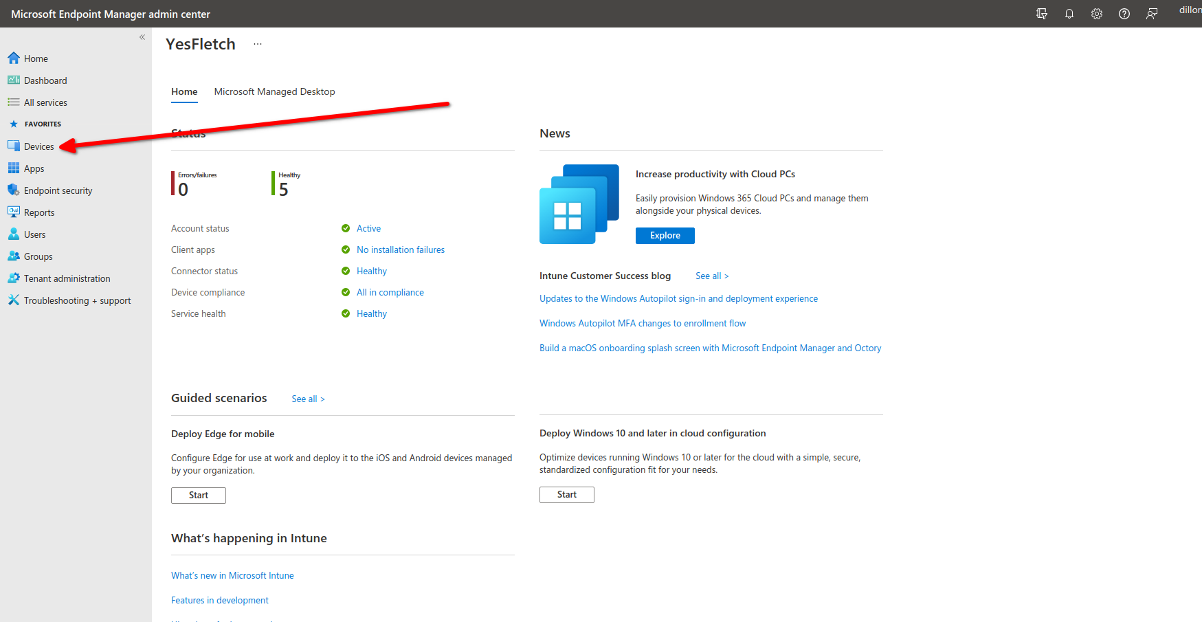
Start by logging into endpoint.microsoft.com, and clicking devices:

Endpoint manager home screen

Clicking this will bring up all devices enrolled into intune:

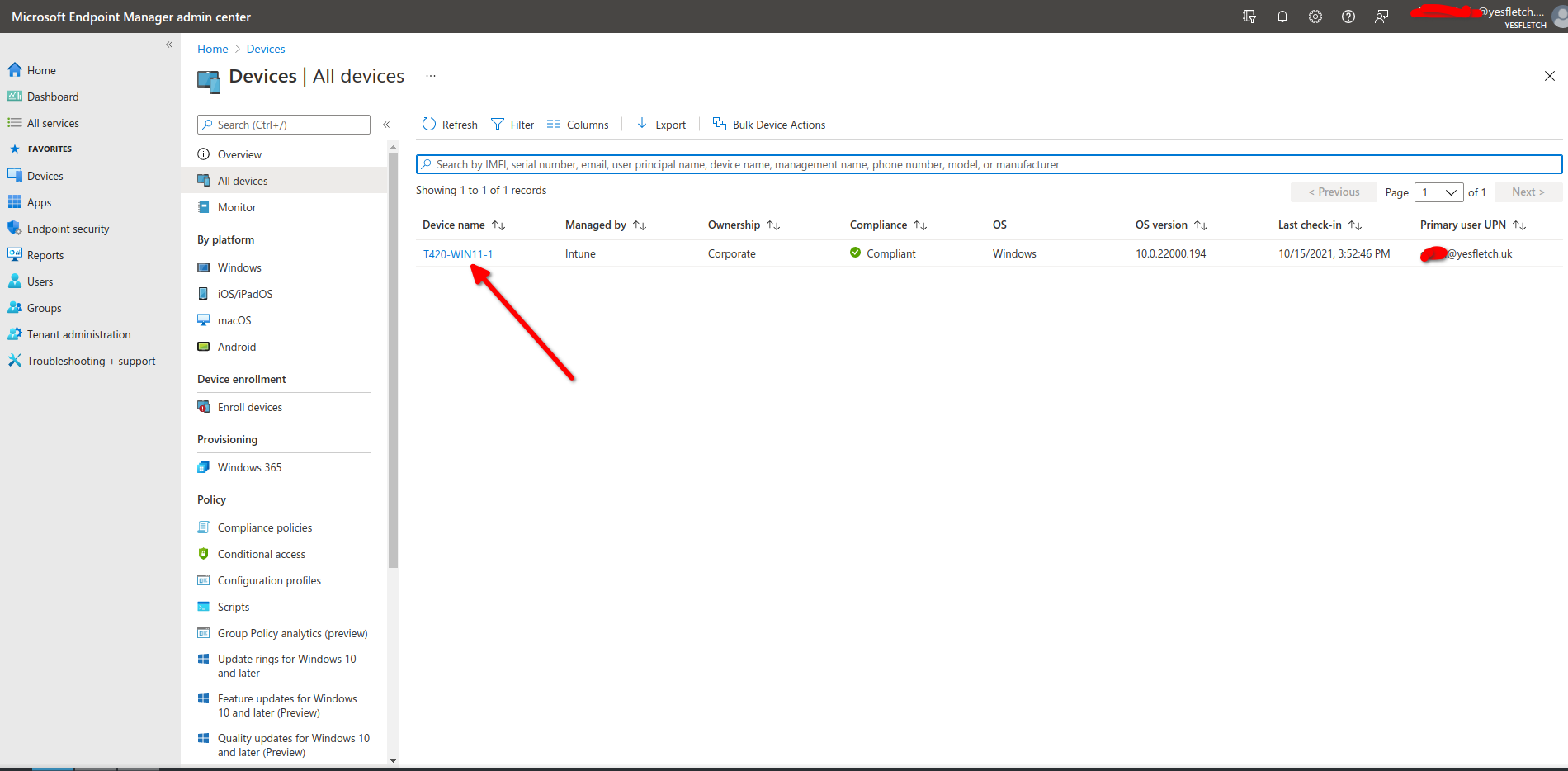
The Thinkpad listed in devices

The device is now listed in endpoint manger, this means enrollment definetly was successful! Now, click on the device name:

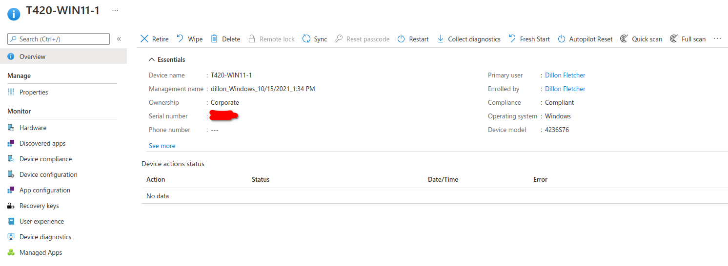
Thinkpad Device Options

This will show device specific options, you can retire, wipe, reboot, Autopilot Reset (reverts device to an OOBE domain joined state), Fresh start (removes all extra Win32 applications), and anti virus scan. On the menu on the left, you can also find device information, such as compliance info, apps installed on the machine, diagnostics, and bitlocker recovery keys.

3. Setup a BitLocker encryption policy

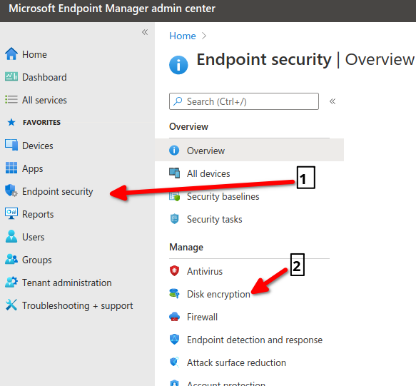
Go back to the home screen and click Endpoint Security, then click Disk Encryption:

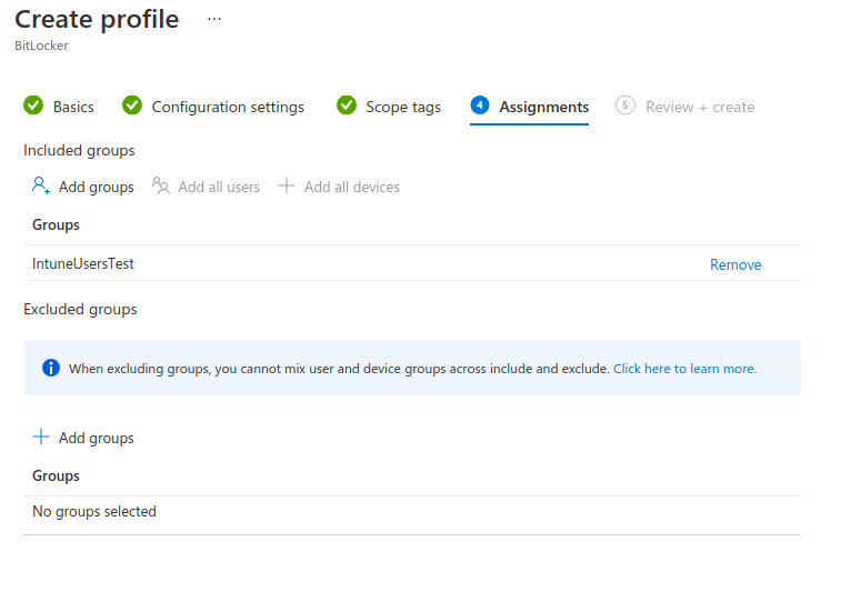
Create a new profile with the following settings:

Now your device should be enrolled into Bitlocker. You can check that all your devices would be compliant by adding a compliance policy. It is a similar process and can be found under “Devices > Compliance Policies”. This is what will trigger the “Compliant” or “Error” under the devices compliant status.

Now sync the device from endpoint device options, and ensure that it begins encrypting:

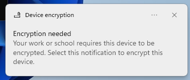
I received this notification on the Thinkpad, meaning that the policy was successfully pushed. I assume this process would normally start automatically, but since my test machine is so old, it doesnt have a TPM chip to store encryption keys on, and clicking the notification prompted me to turn on the TPM in the BIOS. However, it is a good proof of concept I have successfully learnt the basics of Intune! From here, I can learn to push apps/app policies and configuration policies.

Hardening your network

Recently, I’ve been looking into how to improve my networks security. I have come up with 3 simple ways to easily improve your networks security:

1. Setting up an SSH jumpbox

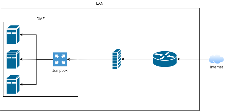
Diagram of how SSH connections will work

One of the only points into my network is via SSH into my web server, this server kind of acts as a jump box already, as I can SSH into my other Linux hosts via password auth, but this isn’t very secure. After some research, I found it was common to have a dedicated Linux host whos only purpose is to “jump” to other machines.

So I started by spinning up a virtual machine, with 1 core, 4GB of RAM and 16GB of storage, running Ubuntu Server 20.04.2LTS, plenty of power for this purpose.

From there, I assigned a static IP and SSH’d in on my computer on the same network.

Now I’m going to go through some important setup.

First, on your local machine, run:

$ ssh-keygen

This will create 2 files in “~/.ssh/”, these are your public and private keys. Do not let your private key leave this computer. With this key, people will be able to access your jump box, think of it as a long, fancy password.

Now on your jump box, we need to add your public key, make sure you are not logged in as root, and preferably make a user without sudo for security. (However, you will need root/sudo for this setup, im assuming you have two separate, non-root users, one with sudo, and one without.)

Now you need to paste the contents of “~/.ssh/id_rsa.pub” from your local computer to “~/.ssh/authorized_keys” on your jump box.

First, on your local computer, run:

$ cat ~/.ssh/id_rsa.pub

Copy the output of this, and on your jump box run:

$ vim ~/.ssh/authorized_keys

This will open a file in vim, you can paste keys on each line, and each key will let you into the server, so I will be repeating the above steps for both my laptop, desktop, and phone (Termbot SSH client).

Once you are done, save the file and then on the jump box, run:

$ sudo vim /etc/ssh/sshd_config

In this file, make these edits:

# Change
#PermitRootLogin prohibit-password
# to
PermitRootLogin no
# and change
#PasswordAuthentication yes
# to
PasswordAuthentication no


This prevents the root user logging in via SSH, and makes it so that we can only login using the keys we added earlier.

Now run:

$ sudo systemctl restart sshd

This restarts SSH, enabling the changes we just made.

If you want, you can also install fail2ban, this “bans” IPs from accessing SSH after 3 failed attempts. This isn’t as neccesary with pubkey authentication, but we are trying to make everything as secure as possible, so, you can do this by running:

$ sudo apt update
$ sudo apt install fail2ban
$ sudo systemctl start fail2ban

Now that everything is secured on the actual authentication side of things, we can forward our SSH port to the internet. Depending on your router/firewall, this process can differ, but it usually consists of finding a page called “port forwarding,” and forwarding port 22 to the IP address of your server, i’m running OPNsense, and the process is as follows:

Copy the output of this, and on your jump box run:

$ vim ~/.ssh/authorized_keys

This will open a file in vim, you can paste keys on each line, and each key will let you into the server, so I will be repeating the above steps for both my laptop, desktop, and phone (Termbot SSH client).

Once you are done, save the file and then on the jump box, run:

$ sudo vim /etc/ssh/sshd_config

In this file, make these edits:

# Change
#PermitRootLogin prohibit-password
# to
PermitRootLogin no
# and change
#PasswordAuthentication yes
# to
PasswordAuthentication no

This prevents the root user logging in via SSH, and makes it so that we can only login using the keys we added earlier.

Now run:

$ sudo systemctl restart sshd

This restarts SSH, enabling the changes we just made.

If you want, you can also install fail2ban, this “bans” IPs from accessing SSH after 3 failed attempts. This isn’t as neccesary with pubkey authentication, but we are trying to make everything as secure as possible, so, you can do this by running:

$ sudo apt update
$ sudo apt install fail2ban
$ sudo systemctl start fail2ban
$ sudo systemctl enable fail2ban

Now that everything is secured on the actual authentication side of things, we can forward our SSH port to the internet. Depending on your router/firewall, this process can differ, but it usually consists of finding a page called “port forwarding,” and forwarding port 22 to the IP address of your server, i’m running OPNsense, and the process is as follows:

  1. Login to your router/firewalls web interface. This is usually the same format as your computers local IP, but with a “1” on the end, my subnet is “192.168.55.0/24” so my web interface is located at “https://192.168.55.1”. Now login, and find the port forwarding page
  2. Add a rule/port forward. Press the add button and fill in the correct info for your port forward, mine is as follows:

Now save the rule, and you should now able to access your jump box from outside of your network.

Now we need to actually harden the jump box itself. I’m going to start by upgrading all packages:

$ sudo apt update
$ sudo apt upgrade
# Reboot for good measure
$ sudo reboot

When the system comes back up, reconnect, and we need to start adding SSH keys to the servers you want to jump to.

So, for example, on my webhost server, I open the authorized_keys file:

$ sudo vim ~/.ssh/authorized_keys

In this file, I paste the contents of ~/.ssh/id_rsa.pub from the jump server, effictively what we are trying to do is restrict ALL SSH traffic to the jump server. The jump server acts as a CNC (“command and control”) server for all other servers and computers running SSH.

Now we edit the SSH config, the same way as before, disabling password and root login.

After that, you should restrict SSH connections to the jumpbox. So open the file “/etc/hosts.deny”:

$ sudo vim /etc/hosts.deny

Add the following:

# /etc/hosts.deny
sshd: ALL

And now we allow just the jump server:

$ sudo vim /etc/hosts.allow
# /etc/hosts.allow
sshd: 192.168.55.250/24
# Your subnet and IP may differ

Now only your jump server can connect, and only with the private key that is on the jump server. Repeat this process for as many servers as you please.

I’m now going to add a few firewall rules, which stop the jump server from connecting to the internet entirely, and again restricts SSH connections to only the jump server. I’m not going to show this as it differs from firewall to firewall and would take up too much space in this article!

And thats it for this step! A few notes:

  • For added security, close the SSH port on your firewall and instead add a VPN, which sole purpose is to allow you connect to the jump server.
  • If you haven’t already figured it out, the only way to connect to other servers via SSH is through the jump server via SSH, this means that you create a ‘tunnel’ through the jump server.
  • Ideally, if you know you wont need to access the server from the outside, you can close the SSH port, or you can add a schedule on your firewall to open and close your port at certain times of the day, you could even use port knocking to make a “secret knock” to open the port temprarily remotely.

2. Intrusion Detection and Intrusion Prevention

Ok, this one is completely unneccesary for home networks, but it is a really useful tool in a business environment. First i’m going to gloss over and explain what an IDS and IPS is.

Intrusion Detection System (IDS):

An Intrusion Detection System, first of all, does not serve the same purpose as a firewall, most of the time the IDS lives on the firewall, which can add to the functionality of your firewall, but it is not a firewall in itself.

An IDS’s purpose is to analyze and detect malicious traffic. It usually does this by checking packet signatures against a list of rules which are known to be malicious traffic.

Intrusion Prevention System (IPS):

An Intrusion Prevention System does everything an IDS does, but also prevents intrusion by usually blocking source and/or destination IP addresses. Most IDS’s have an “IPS” mode which can be enabled.

Setup:

To setup my IPS, I’m going to be installing suricata on my existing OPNsense firewall. I chose suricata because of it’s multithreaded performance, due to all that packet analysis, an IDS/IPS can slow your network down (especially on my older PowerEdge R610 server, due to its poor single thread performance!) However, thanks to multi-threading there is no difference with suricata, I still get my full 150/30 bandwidth performance. However, I also recommend snort, which just newly introduced threading too in its latest version.

So first, I installed the suricata package from the official OPNsense repository:

After installation, go to “Services -> Intrusion Detection -> Administration” and choose your desired settings, mine are as follows:

Now go to “Download” and choose the rule sets you wish to download, I’m not going to go over this though, however I highly recommend this video for explanation and this video for in-depth setup by Lawrence Systems on YouTube.

After you are done, head over to alerts, and you will see a log of all alerts that have been triggered, 99.99% of the time these are going to be bots which are attemptint to access your network. Its even picking up on inbound ports which aren’t even open!

And that’s it for Network Intrusion Detection.

3. Patch Everything!

This one of the most important things you can do, especially with internet facing systems like firewalls or any systems with services exposed. Patching isn’t hard to do, takes little time and prevents people gaining access to your network via known exploits. I’m not going to go through how to patch or update everything because you likely already know how to.

You can find if software you are running is vulnerable on https://www.cvedetails.com/. For example, Apache has had 1457 known CVE’s since 1999 at the time of writing. You can see that DoS vulnerabilities are the most common, followed by Code Execution! This is also why you never run services as root, if an attacker were to find an RCE exploit in apache, they would be dropped into whatever user apache is running as, hopefully for them they will get lucky and the administrator setup Apache to run as root, which means they don’t have to do any more exploitation after gaining a foothold.

Thats it for this post, thank you for reading, and remember to keep your systems secure!

Making a HP ProLiant DL380E G8 suitable for home usage.

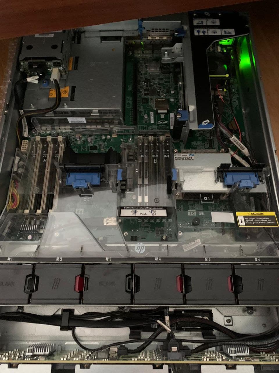
I recently bought a HP ProLiant DL380E G8 from eBay for really cheap. I managed to get ahold of the 27 bay SFF model (2.5″ laptop harddrives.) It’s good mainly for 2 reasons:

1. I can install a GPU into the 16x PCIe riser cage for computational tasks (and some light remote virtual machine gaming!) Thanks to its 2U chassis form factor.

2. I can fill it with as many cheap HDDs as I want!

Part 1: Silencing!

Unfortunately these features come at a cost, it’s really loud! Its fitted with 4 PFR0612XHE Delta Fans, these can spin upto 16500RPM, thanks to the hot P420i RAID card which powers all 27 SAS ports, and that’s great if you are running it in an air conditioned data center, or server room where noise doesn’t matter but for non-professional use we need to find a work around.

So I started searching and I found this reddit post, which allows me manually control the fan thresholds based on certain temperature readings by installing custom iLO 4 firmware, so I could find the sensors for the RAID card, and set the threshold higher. After flashing I can SSH into the iLO and set the threshold for sensor 29, which happens to be my toasty RAID card.

</>hpiLO-> fan pid 29 lo 3500

This command ramps the fans down to a noise level I can barely hear, around 15% according to iLO:

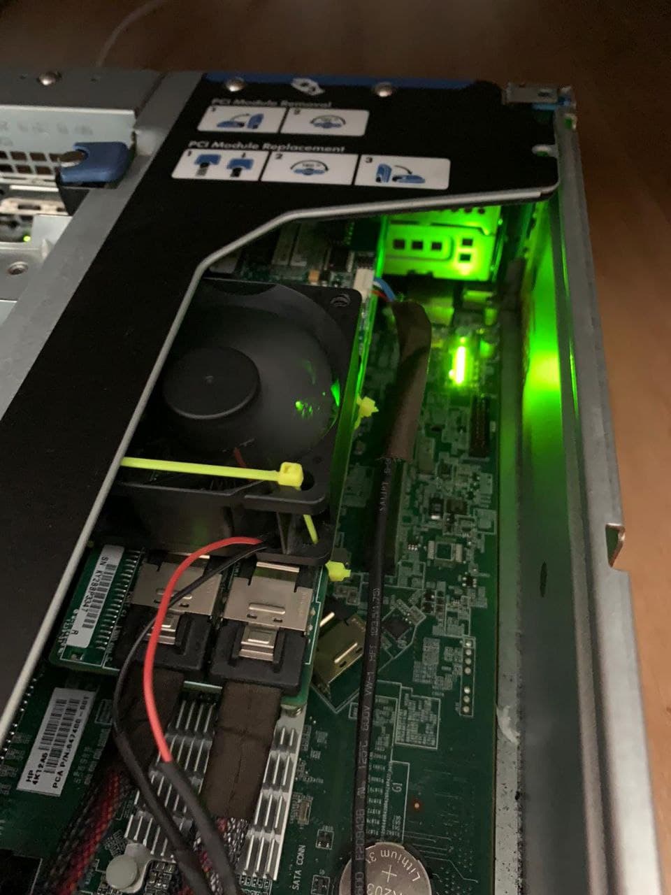
Now this presents a new problem, the RAID card, now with no cooling is hitting temperatures upwards of 95C. This is far too hot and at 100C the system will shutdown due to thermal protection. So I decided I would “fit” a fan, salvaged from an old Sky TV Box ontop of the P420i’s heatsink. I soldered a USB connector onto the fans positive and negative wires, making sure to properly isolate both wires. I could then connect it to the servers internal USB port and zip tie the fan onto the RAID card, making sure its tight enough to not fall off and loose enough to not destroy the surface mount components.

It didn’t turn out too bad, it wasn’t exactly a professional job and should be considered a hacky work around, but it keeps the card at a cooler 75-80C (it’s still hot, just safe enough to not cause a thermal shutdown.)

Part 2: Upgrading

The server came with a single Xeon E5-2420 (6c/12t @ 1.9GHz.) It’s not exactly high-performance by todays standards, but it does the job for now. I plan to upgrade to a power efficient Xeon E5-2450L V2 (10c/20t @ 1.7GHz) for virtualization, I could theoretically also put in a second CPU in the future, and have up to 40 threads, but 20 threads is more than enough.

It also came with 12GB (3x 4GB) of Samsung ECC Reg Memory. Which isn’t really enough, I simply took 2 8GB ECC sticks out of my desktop as I don’t really need 32GB in my desktop, and put them in the same channel as each other, as I am mixing Samsung sticks with SK Hynix sticks. I now have 28GB of RAM, which should be enough. for several Virtual Machines.

Part 3: OS

I’ve decided to go with Proxmox VE, as it is my favourite hypervisor, it’s based on Debian so it’s familiar to me, and it can run both KVM Virtual Machines and LXC containers. It also supports clustering, ceph storage and has a fairly easy to use web interface.

And that’s it for now. Thanks for reading!

Using a free VPS as a dedicated IP for virtual machines.

I recently wanted to setup an Ubuntu virtual machine on my Proxmox server so that my friends and I could share a server for hosting things on. The issue was that I am currently using the default ports for the services we wanted to run on my existing internet connection. So the obvious options were as follows:

  1. Run the new services on non-default ports.
  2. Pay for a second internet connection/second IP address.

This either costs money, or causes unneccesary hassel. This is where the VPS comes in, im using an Amazon Web Services t2.micro instance based in London, (as close as possible to home to avoid performance issues), but you can use any server with a dedicated IP or DMZ which you aren’t using for any other services, ideally with a dedicated IP so not to cause double NAT issues.

So, to start, I’m assuming you have both your client (my local VM) and your server (my remote VPS) setup with Ubuntu and connected to the internet. On both machines, begin by installing wireguard, we are going to use wireguard to create a VPN tunnel between the VPS (server) and the VM (client).

$ sudo apt update
$ sudo apt install wireguard

Now we need to generate a public and private key. This command uses generates a private key, with the ‘wg genkey’ command, creates a file called privatekey, then pipes the output of ‘wg genkey’ into ‘wg pubkey’, which takes the private key and outputs a matching public key, again, run the following command on both the client and the server.

$ wg genkey | sudo tee /etc/wireguard/privatekey | wg pubkey | sudo tee /etc/wireguard/publickey

You should now have 2 files in ‘/etc/wireguard’, ‘publickey’, and ‘privatekey’. You can view them using the ‘cat’ command. You will need them later.

We now need to begin creating our config files for the wireguard VPN interface. We can start on the server, begin by running:

$ sudo vim /etc/wireguard/wg0.conf

This creates the file wg0.conf in /etc/wireguard, in the command above im using vim, but you can use your preferred text editor. In the file you should insert the following, making sure to replace the PublicKey with the public key from the client, and PrivateKey with the private key from the server.

[Interface]
Address = 10.66.66.1/32
ListenPort = 51820
PrivateKey = <Server PrivateKey here>
PostUp = iptables -t nat -A POSTROUTING -o eth0 -j MASQUERADE; ip6tables -t nat -A POSTROUTING -o eth0 -j MASQUERADE
PostDown = iptables -t nat -D POSTROUTING -o eth0 -j MASQUERADE; ip6tables -t nat -D POSTROUTING -o eth0 -j MASQUERADE

[Peer]
PublicKey = <Client PublicKey here>
AllowedIPs = 10.66.66.2/32

The ‘PostUp’ and ‘PostDown’ sections enable NAT on the VPN to allow the client to connect to the internet via the server.

Now open the same file on the client but instead insert this:

[Interface]
PrivateKey = <Client PrivateKey here>
Address = 10.66.66.2/32

[Peer]
PublicKey = <Server Privatekey here>
Endpoint = <Server IP Address Here>:51820
AllowedIPs = 0.0.0.0/0

Same thing as before, but we need to set the endpoint to the server, and the PrivateKey and PublicKey are swapped.

Now run on both the client and the server:

$ sudo wg-quick up wg0

This will set the interface ‘wg0’ up and start wireguard, creating a tunnel between both machines.

You can check the connection is successful by seeing if you can ping the client from the server, run this on the client:

$ ping 10.66.66.1

If you did everything correctly, you should see the following output!:

PING 10.66.66.1 (10.66.66.1) 56(84) bytes of data.
64 bytes from 10.66.66.1: icmp_seq=1 ttl=64 time=14.6 ms
64 bytes from 10.66.66.1: icmp_seq=2 ttl=64 time=15.3 ms
64 bytes from 10.66.66.1: icmp_seq=3 ttl=64 time=15.5 ms
64 bytes from 10.66.66.1: icmp_seq=4 ttl=64 time=15.5 ms
--- 10.66.66.1 ping statistics ---
4 packets transmitted, 4 received, 0% packet loss, time 3005ms
rtt min/avg/max/mdev = 14.612/15.224/15.500/0.358 ms

You can also use ‘wg show’ to check the connection.

$ wg show
interface: wg0
  public key: (hidden)
  private key: (hidden)
  listening port: 54832
  fwmark: 0xca6c

peer: 
  endpoint: (hidden)
  allowed ips: 0.0.0.0/0, ::/0
  latest handshake: 1 minute, 20 seconds ago
  transfer: 663.55 MiB received, 87.98 MiB sent

On both the client and the server, run this command to start up the VPN on boot.

$ sudo systemctl enable wg-quick@wg0

Almost there! We are done on the client now, we just need to enable some iptable rules on the server, to forward all ports from the server to the client via the VPN tunnel.

Run this script on the server:

sudo iptables -A FORWARD -i eth0 -o wg0 -p tcp --syn --dport 1:21 -m conntrack --ctstate NEW -j ACCEPT
sudo iptables -A FORWARD -i eth0 -o wg0 -p tcp --syn --dport 23:51819 -m conntrack --ctstate NEW -j ACCEPT
sudo iptables -A FORWARD -i eth0 -o wg0 -p tcp --syn --dport 51821:65535 -m conntrack --ctstate NEW -j ACCEPT
sudo iptables -A FORWARD -i eth0 -o wg0 -m conntrack --ctstate ESTABLISHED,RELATED -j ACCEPT
sudo iptables -A FORWARD -i wg0 -o eth0 -m conntrack --ctstate ESTABLISHED,RELATED -j ACCEPT
sudo iptables -t nat -A PREROUTING -i eth0 -p tcp --dport 1:21 -j DNAT --to-destination 10.66.66.2
sudo iptables -t nat -A PREROUTING -i eth0 -p tcp --dport 23:51819 -j DNAT --to-destination 10.66.66.2
sudo iptables -t nat -A PREROUTING -i eth0 -p tcp --dport 51821:65535 -j DNAT --to-destination 10.66.66.2

And thats it! Thanks for reading, the only things you need to know now are:

The only ports you won’t be able to use now are 51820, and 22, because they are in use by the server.

  • You should now be able to access the clients ports and services on the IP address that was assigned to the server!
  • I would highly reccommend installing UFW firewall on the client.
  • DO NOT use these rules in a production environment! I am using a disposable VPS
  • If you want to be extra safe you should manually forward the ports you need from the server.